

All process plants exhibit flow induced vibration to some degree in their piping systems. This may lead to process outages, reduced flowrate restrictions or failure in some cases. Here we discuss how to head off problems at the design stage and how to address problems once found.
The Problem
Unsurprisingly, vibration of piping causes stresses in the pipe wall that can lead to fatigue failure after enough cycles. These cycles accumulate fairly rapidly – for continuous vibration at a dominant frequency of 2Hz (the low end of the probable range), there are 10 million cycles in 58 days. This is enough to cause failure in many cases. Higher frequencies offer proportionately less time for action.
Cause of the issue
Fittings, valves and other flow disturbances generate turbulence and pressure fluctuations. With increasing flowrates or more disturbances in proximity, the turbulence increases in intensity. In locations where the pipe is not well restrained it has low natural frequency modes of vibration which get excited by these fluctuations, leading to noticeable vibration. Typical pipe layout features which are prone to vibration are large overhangs with a change of direction, pipe supported on springs or with few guides.
Another common cause is flashing and cavitation downstream of control valves, or recycle valves operating with a high flow and pressure drop, cavitating pumps or two phase flow. These generate more intense shaking forces than turbulence alone, exciting pipes which might otherwise be sufficiently restrained.
Design stage – screening
The Energy Institute Guidelines Likelihood of Failure (LoF) check gives a screening method for pipe DN750 and below. FIV tends to be exacerbated by high flow and density (more specifically 
A less rigidly supported system is more easily excited by turbulent forces. That’s why there are minimum natural frequencies specified in some pipe stress procedures. Typical hurdle values may be 4Hz for general process piping and 7Hz for blowdown and other vibration-prone lines. Recent EI guidelines for subsea piping suggest the use of 7Hz as a minimum criterion.
There is always a trade off between design for thermal nozzle load or stress (less restraint is better), and design for prevention of vibration (more restraint is better). This can be problematic when there are low allowable nozzle loads, such as at rotating equipment. This can lead to a system which doesn’t meet the desired lowest natural frequency. Where minimum natural frequencies can’t be achieved it is advisable to conduct vibration monitoring during commissioning, or to design in additional dynamic restraints.
Ways to reduce vibration ahead of time
- Increasing pipe size or splitting into two streams
- Pipe routing to reduce turbulence generation
- Additional static pipe supports
- Addition of dynamic pipe supports
- Be wary of over-economising, with respect to pipe wall thickness, diameter, member size, avoidance of vibration studies.
- Remember to re-visit studies before debottlenecking or significant operational changes
Depending on project budget and design philosophy, there may be additional dynamic stress analysis carried out. This will be similar to that addressed further on this article, without the field measurement aspect.
Field Vibration – identification
Often the first inkling of trouble is when field personnel notice the pipe shaking either during commissioning, or in operation at certain flow rates. Questions that immediately arise include:
- Is it safe to keep operating?
- Will the vibration damage attached equipment?
- How much should we reduce the flow to keep vibration to a safe level?
- If it is acceptable now, how much can we increase flowrates before unacceptable vibration?
By taking vibration readings, we can quickly generate preliminary answers to these questions.
Initial screening
The Operator or a specialist subcontractor takes vibration velocity measurements by attaching an accelerometer to the pipe at high displacement locations. These are then compared to company standard velocity limits to quickly determine the seriousness of the issue. If there is no company standard then use a suitable industry standard like the Energy Institute Guidelines.
If velocity limits are exceeded, it may still be acceptable to continue operating if it can be demonstrated safe by stress analysis. While the stress analysis is in progress however, it’s advisable to reduce flowrates or take measures such as provision of temporary strops or scaffold guides.
Investigation and Resolution
At its simplest, we reduce vibration by placing additional restraints at locations with high movement. If the line operates at close to ambient temperature, it is probably safe to add restraints in the areas which are moving most. In many cases, there is a pipe support with guide gaps that need to be closed up, or there is a support that’s flexing. In this case, stiffening the support steel may be enough to control the problem.
When to get a stress engineer involved
When should you get a stress engineer involved?
- If it’s not immediately obvious what changes should be made
- if you want to check the potential for fatigue failure
- check the safe operating range
- Line is stress critical
The stress criticality of the line should be checked – if it’s listed as stress critical on your process line list then have any changes reviewed by a stress engineer.
When a stress engineer gets involved he or she typically analyses the system and extracts the first few mode shapes, i.e. the natural frequencies and corresponding vibration shapes. Then they seek to place restraints at locations with high modal displacements. They need to check the effect on the static analysis as well, i.e. that nozzles aren’t overloaded, pipe overstressed or support loads excessive.

Dynamic Stress analysis
At a slightly higher level of sophistication (and to assess whether safe to continue operation) the stress engineer simulates the vibration in a dynamic model, trying to approximate field vibration shapes, displacement magnitudes and alternating stresses. There is usually little point in ‘counting cycles’ with vibration as they accumulate so quickly. Rather, the pipe is safe to continue operation if the calculated alternating stress is below the fatigue endurance limit, with a reasonable margin for error. For fatigue assessment we use an agreed standard such as EN13445, ASME VIII Div. 2, DNVGL RP-C203 or BS 7608.
The simulation would typically use frequency domain (response spectrum) methods, either by applying a load-frequency spectrum at elbows, or by ‘shaking’ the pipe supports, as in an earthquake. The ‘equivalent earthquake’ approach is pretty good at simulating piping vibration, which is usually dominated by the first few modes.
Model calibration
Desktop simulations should be calibrated against real world results if available, using measured field vibration velocities. This is a process of scaling and tweaking inputs to best match field values.
While not widely used at this time, motion amplification cameras can be useful for calibration. Most stress programs output dynamic displacements, but not vibration velocities. The motion amplification software provides estimates of displacement for comparison.
We can use a Matlab script to process CAESAR II results and calculate velocities. Or we use pipe stress software such as ROHR2 or CSiPlant, which offer more dynamic capabilities including calculation of dynamic velocities and accelerations.
The likely effect of various pipe support modifications and flow rate changes can be simulated. Then we can estimate the reduction in vibration displacements, stresses and velocities.
Time history method
Time-history modelling approaches can be used to offer more insight than frequency domain methods. We synthesise the time-based forcing function using shaped white noise. This can offer less conservative stresses and nozzle load calculations via point-in-time results. (Frequency domain methods are conservative as there is no way to know whether modal responses are simultaneous or not, therefore they must be combined using a convention such as the ‘square root of the sum of the squares’).
More representative modelling of real world supports can be achieved in the time domain with ROHR2 or CSiPlant, such as accounting for guide gaps and friction. It’s also possible to simulate dynamic restraints like sway braces and viscous dampers (covered below). These special restraint types are useful if new static guides and line stops would cause thermal stress or nozzle load exceedances. These can also be modelled in most popular stress programs but it’s necessary to make approximations (ie. everything is modelled as a pseudo-spring).
Dynamic Support – Sway Brace
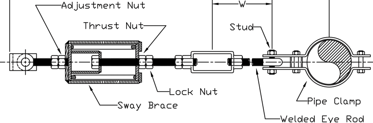
Sway braces have a spring with a preset load which is not applied to the pipe but rather is contained by the housing. In this way it is similar to a ‘topped out’ conventional spring support. The design shown in the figure permits the connecting rod to push the spring in either direction. Thus it offers a fixed resistance in the positive or negative direction up to the preset ‘yield’ point, after which it again acts as a spring. Therefore it can be set to offer just enough resistance to keep vibration under control in cases where thermal reactions might otherwise be too high.

Dynamic Support – Viscous dampers
These dampers offer resistance which is (ideally) proportional to velocity of movement. In this way they allow static expansion and contraction with little or no resistance, but react strongly against vibration.

These supports consist of a piston in a container full of viscous fluid. They react to dynamic movement in any direction, giving them an inherent advantage over sway braces. Generally the horizontal resistance is greater than the vertical resistance by a factor of 2 or more. Stiffness is defined in terms of Force per unit of velocity, and it varies with the frequency of movement. Therefore, if simulating these in conventional software like CAESAR, it is necessary to define the major excitation frequency and derive a stiffness for modelling as an equivalent spring.
The load plate can be attached to pipe and the base plate to structure beneath, or the base plate attached to pipe and the load plate attached to structure overhead. Either of these ways will work with little difference. Note that there is an addition of weight to the pipe. The dampers do not provide any static support so the pipe must be supported independently.
In our opinion, for the relatively low cost of purchasing these items, it is worth designing and specifying these in advance for certain critical vibration-prone piping. This may include larger lines attached to rotating equipment or with high pressure ratio letdown / recycle valves.
Note: hydraulic shock arrestors / snubbers are sometimes mistakenly specified for vibration restraint. While they may be effective in some cases, they are not designed for large numbers of cycles. The mechanical parts will most likely wear out quickly.
Final word
Piping vibration is a prevalent issue and one of the most common causes of loss of containment. Wherever possible, its worth preventing up-front in the design stage using screening and predictive analysis. When it’s too late for that, field vibration measurement can be used to compare to industry or company standard limits. A dynamic stress analysis by an experienced stress engineer can determine the risk with less conservatism, and if applicable design a solution to restrain the piping for safe operation.
If your plant has concerning piping vibration or you want to head it off in advance, please get in touch to discuss your issue.